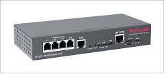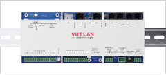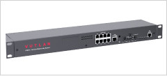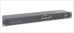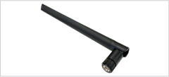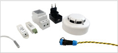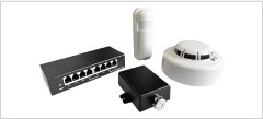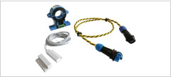
Total control over your infrastructure environment.

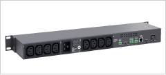
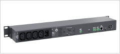
The VT855G Gigabit Corporate Data Center monitoring unit can be used for remote environmental monitoring in corporate data centers. Its primary features include:

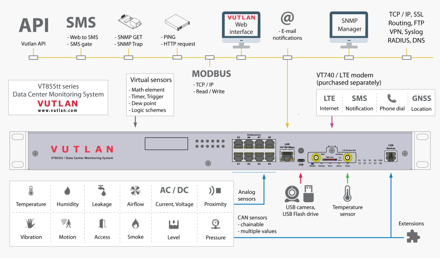
- Environmental Monitoring: Measures temperature, humidity, voltage, access, smoke, dust, vibration, access, leakage, movement, airflow.
- I/O Controller: 8 analog inputs, 2 CAN inputs, 32 digital dry contacts IN and 8 OUT, 4 relays, SD, USB, extensions.
- Scalability: Supports up to 1500 elements, including sensors, virtual sensors, logic, notifications.
- Ethernet: 10/100/1000Mbit/s.
- Extensions: 4G, 5G modem, Modbus, OSDP v2 Reader.
- Notifications: Telegram, mail; VPN, SMS and voice call in case of modem built-IN.
- Processor: 1Ghz dual-core Cortex-A7, 128Mbit RAM.
- Redundant power supply: AC or DC or a mix

Use cases

The VT855G is a powerful gigabit level device that takes corporate data center operations to the next level.

Order options

VT855G unit provides redundant power backup capability. See order options below:

VT855G:
230 VAC power input.
VT855GG :
Two 230 VAC power inputs provide backup power.
VT855DC :
24-48V DC power input.
VT855DCDC :
Two 24-48V DC power inputs providing a redundant power supply.
VT855GDC :
230V AC power and 24-48V DC power inputs. Redundancy supported.

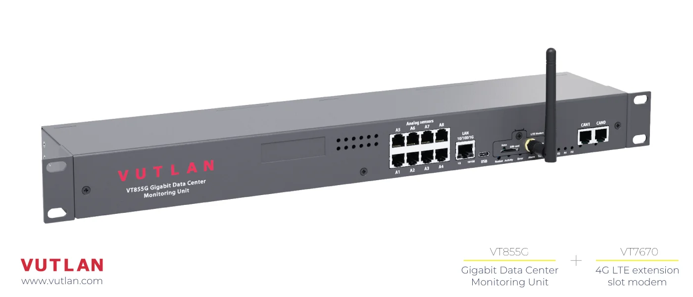
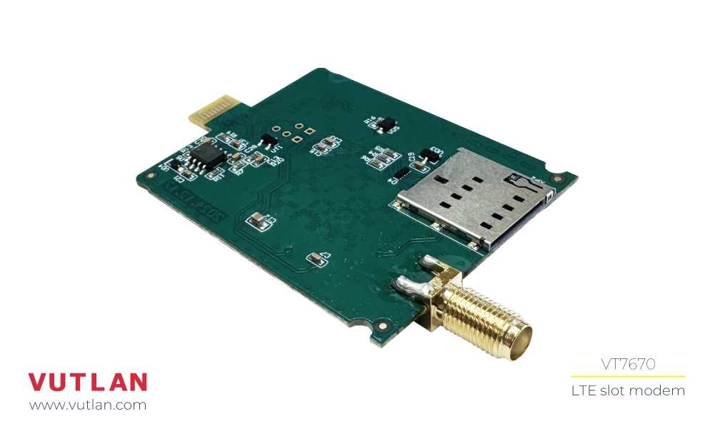
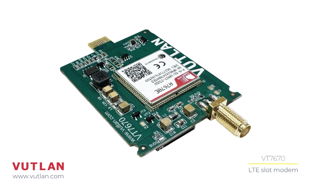
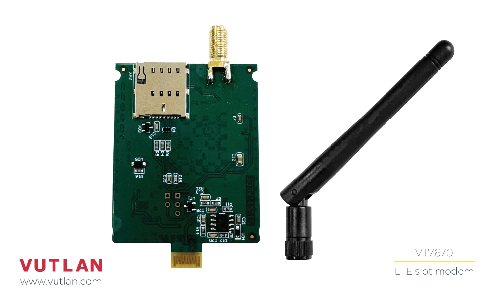
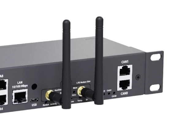
Extension: 4G LTE modem slot

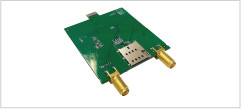
The VT7670E & VT7670G 4G modems support receiving and sending SMS messages via 2G, as well as providing Ethernet connectivity over LTE (4G).

Supports network redundancy; if the LAN connection fails, the module automatically switches to LTE 4G to maintain the Ethernet connection.

This plug-and-play board is inserted into the modem slot of Vutlan monitoring units.

VT7670E is best suited for the European region. VT7670G is best suited for the rest of the world.

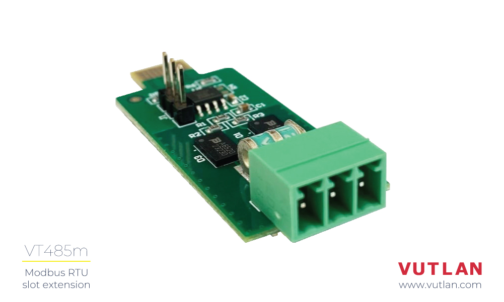
Extension: VT485m or VT485r

You can install either VT485m or VT485r extension.

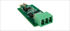
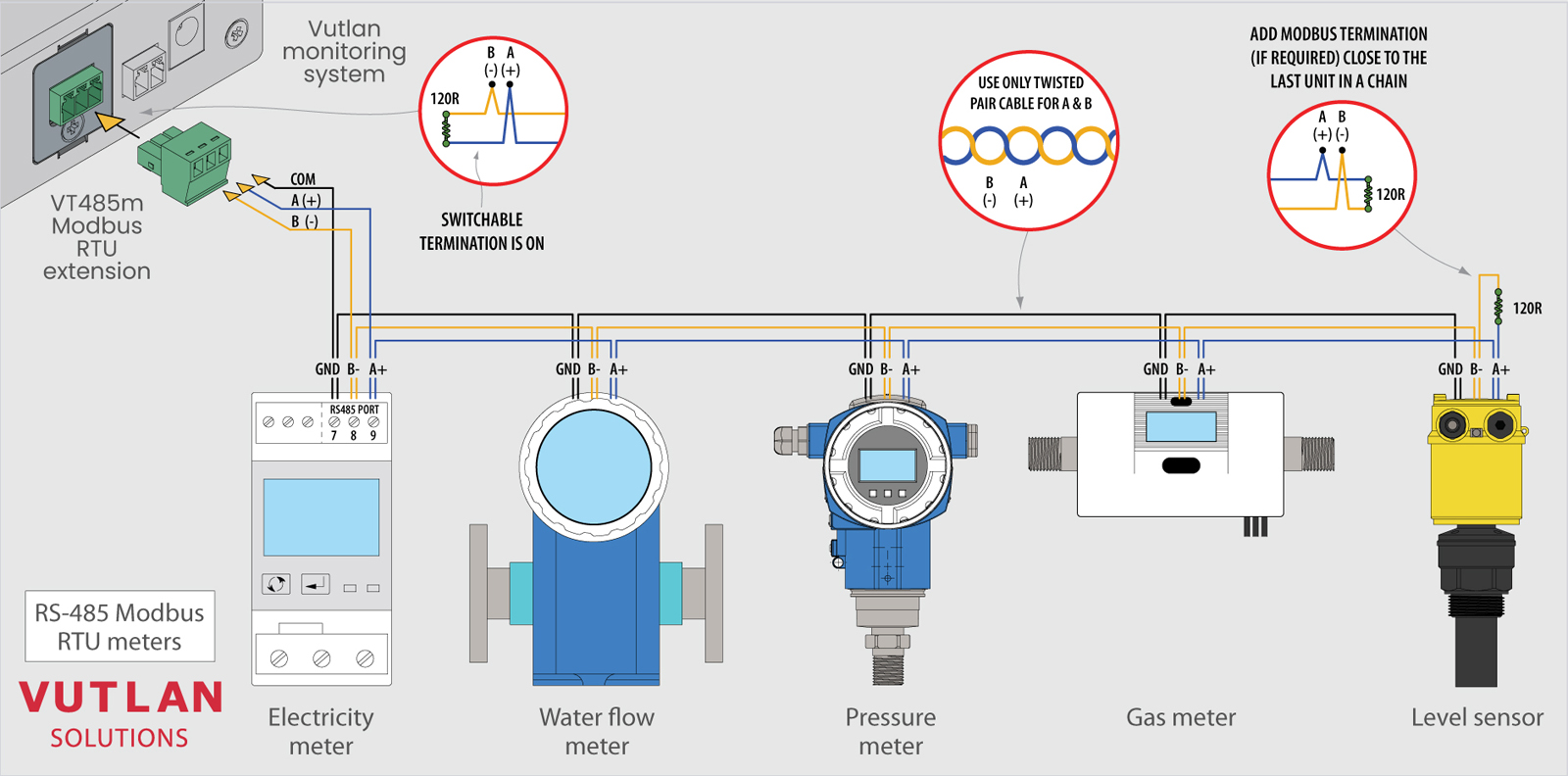
The VT485M Modbus Expansion Board transmits measured data from Modbus devices to the Vutlan monitoring device.

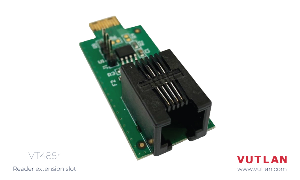
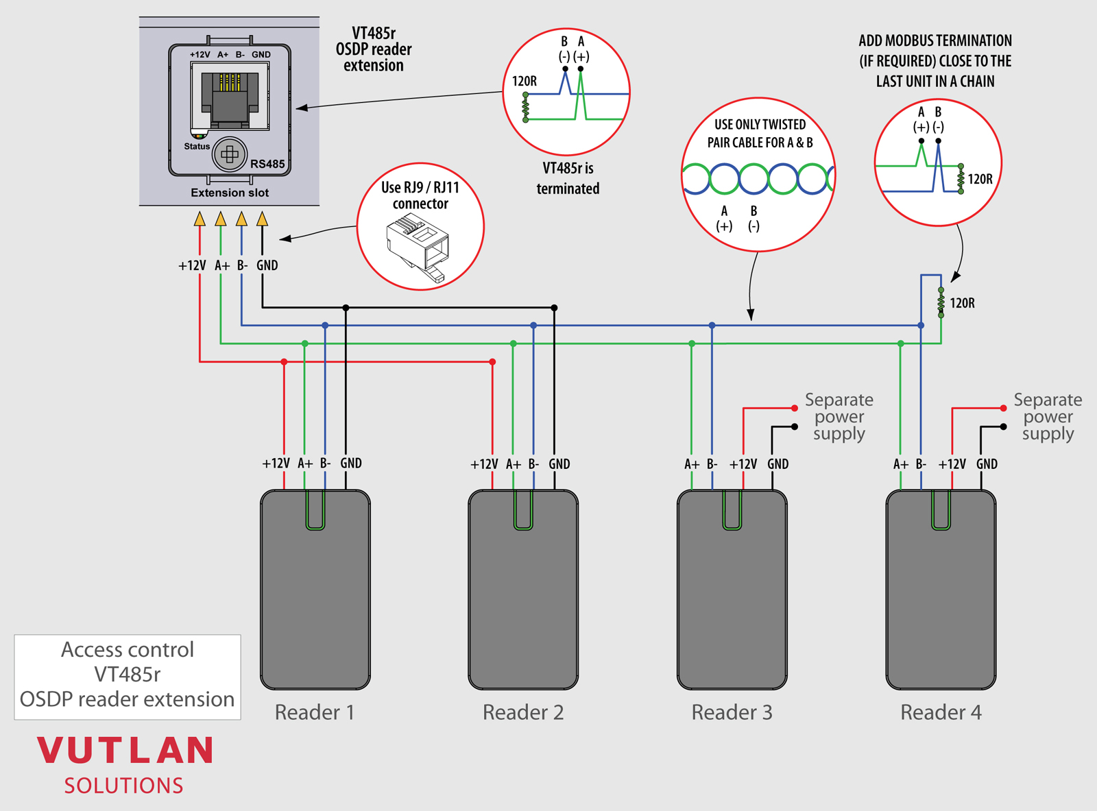
The VT485r is an extension PCB board that allows for the connection of readers and keypads that support the OSDP protocol.

Extension: VT-ACCU

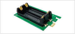
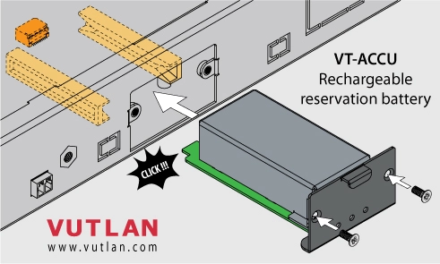
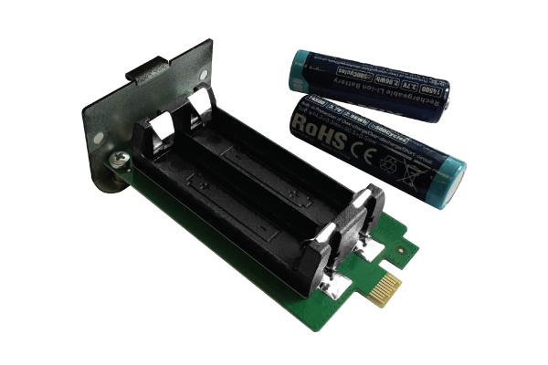
VT855G has a slot for installing VT-ACCU Battery backup board extenion.

The VT-ACCU backup power supply board is an expansion module designed to ensure continuous operation of Vutlan monitoring units. It charges when the unit is powered and automatically provides backup power when the input voltage drops. Once power is restored, the batteries begin charging, ensuring constant readiness for operation.

Advanced protocols

Vutlan supports most popular communication protocols & adding more...

SNMP v1, v2c, v3

Simple Network Protocol for connecting multiple Vutlan units to a single DCIM, NMS, and Infrastructure monitoring software.

+

Modbus RTU,
Modbus TCP

Modbus serial communication protocol designed for industrial automation systems, and industrial meters.

+

OSDPv2 RS485

Open Supervised Device Protocol is an access control communications standard for readers, & keypads.

+

and other...

DHCP, HTTP, HTTPS, SMTP, FTP, Syslog, TLS, DynDNS, RADIUS, SSL, NTP, OpenVPN

Complete Control

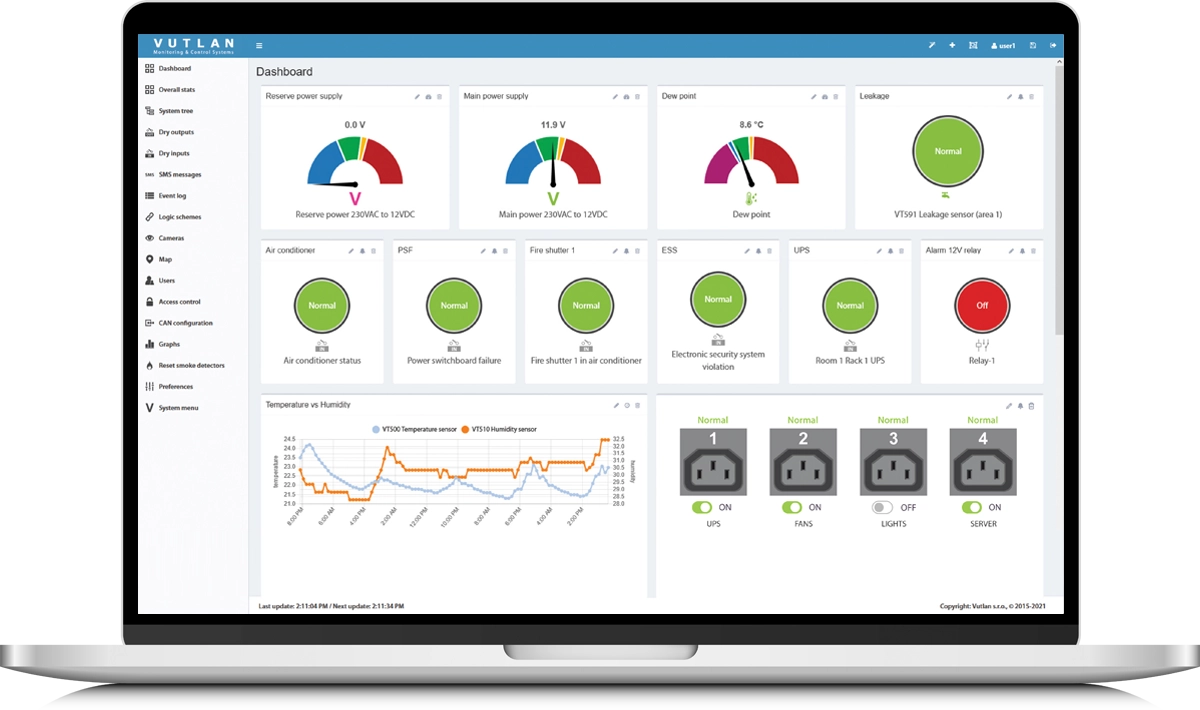
Monitor devices, transform sensor data into actionable insights, and configure integrations — all within an intuitive web-based interface.

- Monitor real-time data from all connected sensors & devices
- Create automated actions based on defined conditions
- Send Email, Telegram, HTTP request, SNMP or other notifications
- Visualize trends and logs for better decision-making
- Manage users, permissions, and access securely

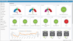
Dashboard: The interface can be customized for each user and display the most important information about system elements, sensors and devices.

Optional Expansion via CAN Bus

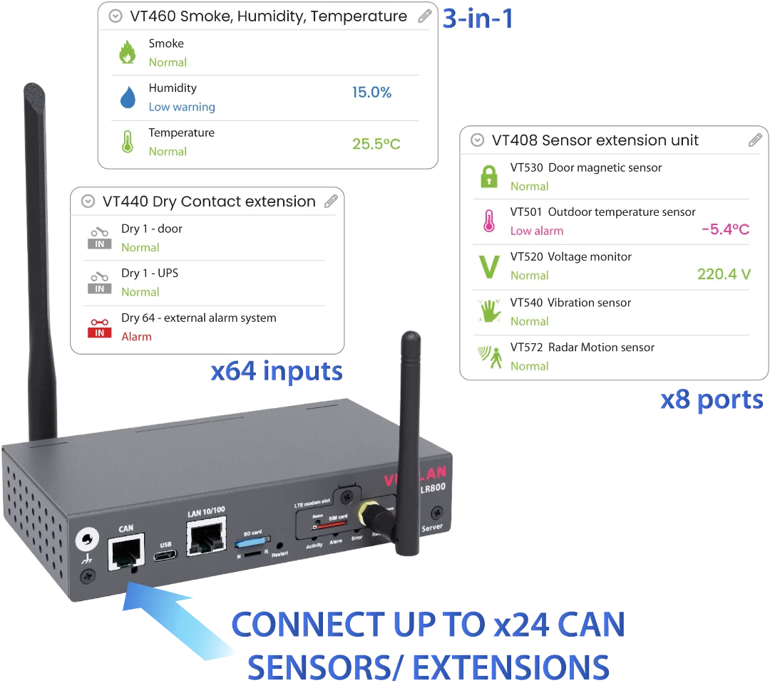
Expand your setup using the LR800’s CAN port by connecting additional sensors and extension modules in a single chain. This optional capability lets you adapt the system to your specific requirements when needed.

- Connect up to 24 CAN devices/sensors in one CAN chain
- Add VT408 Analog Sensor Extension Modules
- Add VT440 Dry Contact Extension Modules

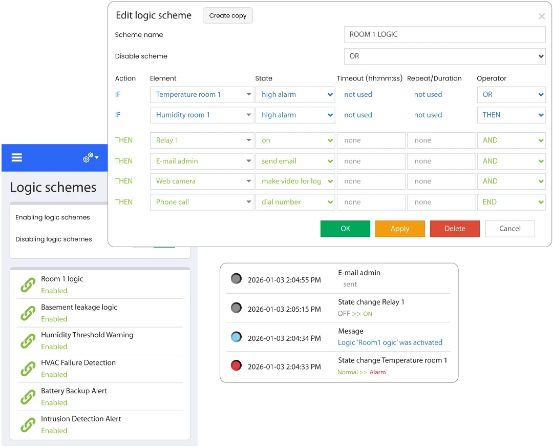
Automated Event Action Response

Logic diagrams enable automated workflows that instantly respond to system events. By defining custom conditions and triggers, the LR800 gateway server can take immediate action without manual intervention.

The system delivers real-time notifications via Email, Push, Telegram, SMS, Syslog, Event Log, SNMP Trap, and SNMP Get, while also triggering physical actions such as signal beacons for on-site alerts.

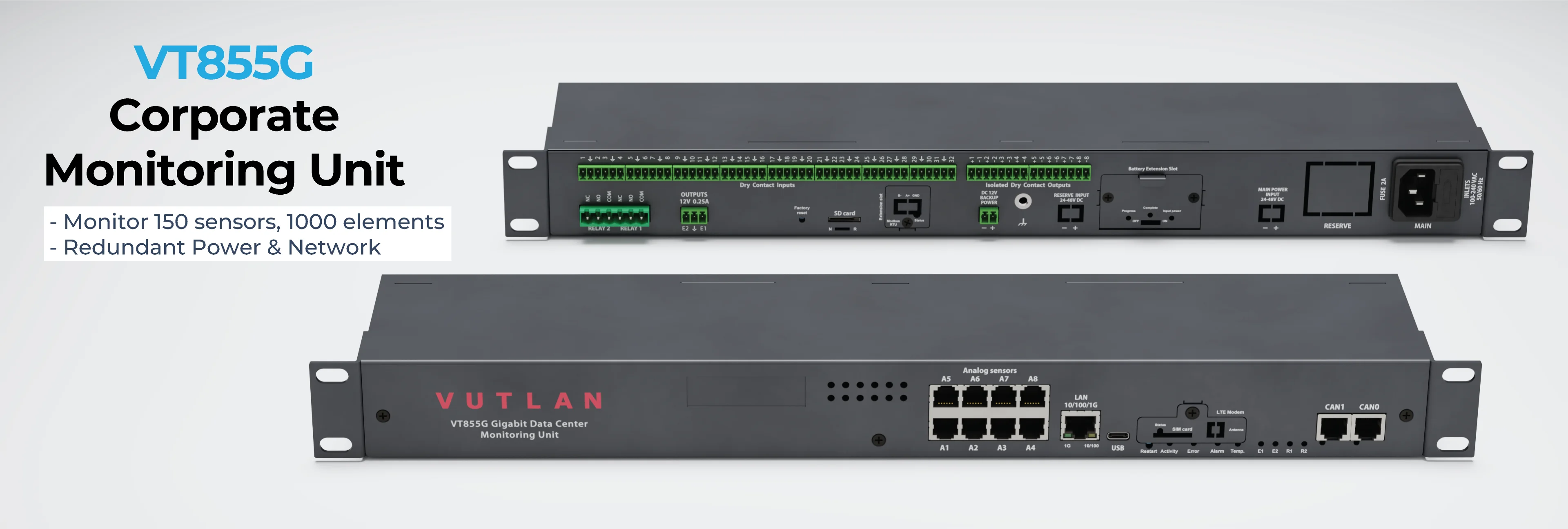
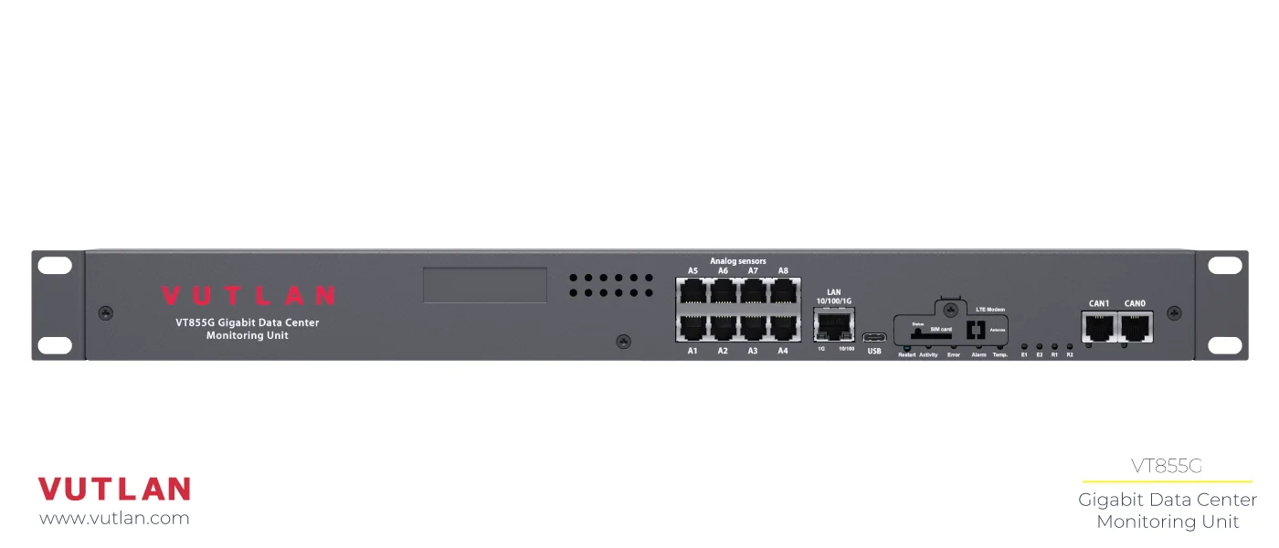
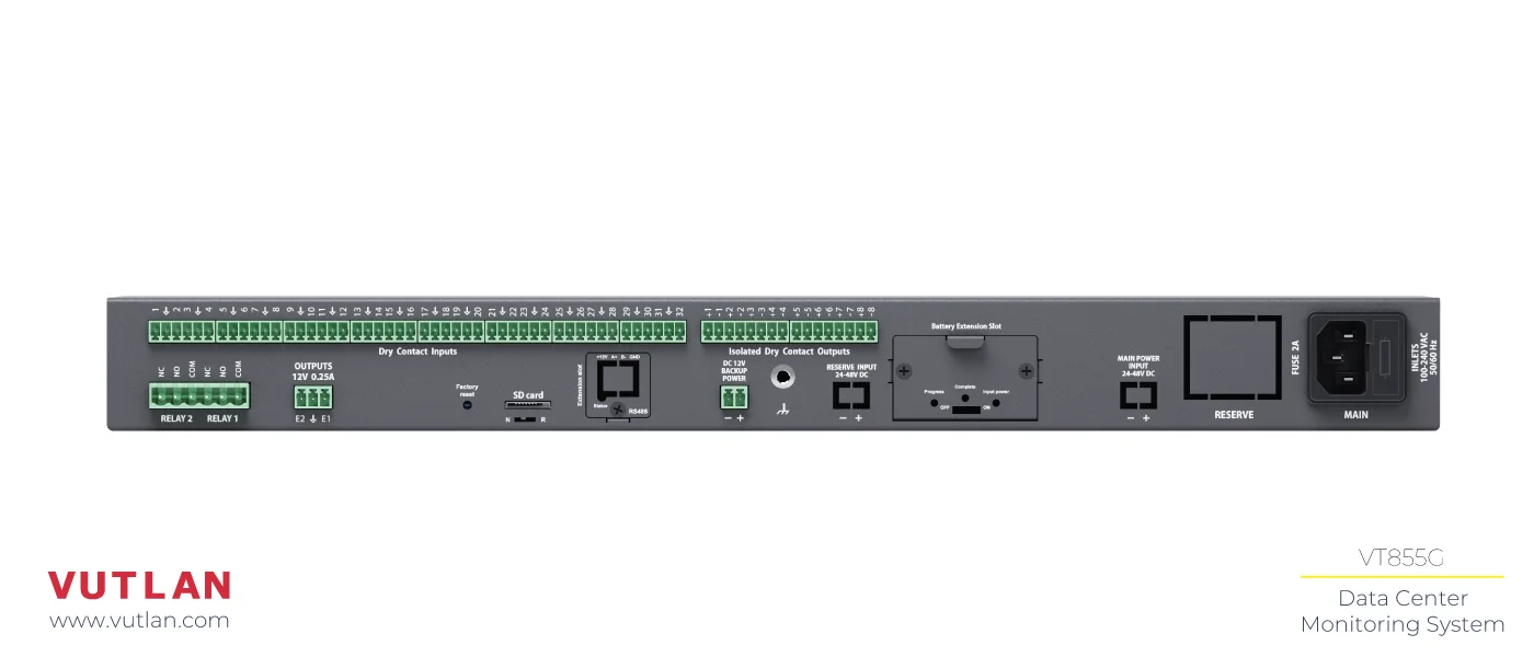
Physical Description

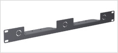
1. 1U 19-inch brackets
x2 pcs for mounting brackets into a 1U 19" rack slot.
2. Sticker space
A place for a sticker
3. Analog ports
x8 RJ12 analog sensor inputs with auto-sensing.
4. LAN port
Ethernet 10/100/1000 Base-T port for Ethernet/LAN
5. Modem slot
(ordered separately)
Allows to receive and send messages (2G, 3G). Provides Ethernet over LTE (4G).
6. CAN ports
Connect up to x24 CAN extensions or sensors in a chain.
7. USB port
Micro USB ports is needed for USB camera recording, USB Flash for system logs, and system restoration.
8. Restart
The button restarts the appliance.
9. LEDs
System activity, error and alarm
10. Temperature sensor
Internal sensor, accuracy +/- 1 °C.
11. LEDs E1, E2, R1, R2
LED status indicators for 12V 0.25A Relay Outputs and x2 NC/NO/COM relays.
12. Dry contact inputs
x32 Digital inputs (Type IN) for connecting dry contact sensors or receiving alert signals from external equipment.
13. Isolated Dry Contact Outputs
x8 dry contact outputs 24VDC / 15mA (type OUT).
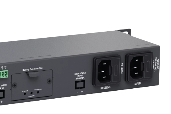
14. Battery Extension Slot
Extension slot for “VT-ACCU / Rechargeable reservation battery”
15. Reserve AC power input
Reserve power inlet. 100-240VAC, 50/60Hz, Fuse 2A, Fuse 5x20mm, type C14. Optional
16. Main AC power input
Power inlet. 100-240VAC, 50/60Hz, type C14. Optional.
17. Fuse
Fuse 2A, Fuse 5x20mm
18. Relays 1 & 2
NC/NO/COM power relay terminals.
19. 12V electronic relays
For controlling x2 low-power devices, i.e. alarm beacons, a siren and/or strobe light, or other.
20. Factory reset
Reset settings to default factory settings.
21. N - R switch
Normal mode & Restore of appliance mode
22. Micro SD card slot
For data storage of logs (SDXC up to 512 Gb, up to x3 years) or system update.
23. Extension slot
Only one of the two extensions can be installed “VT485m / Modbus RTU extension” or “VT485r / OSDP v2 reader extension”.
24. DC 12V Backup Power
12V, DC (3.81 mm, 2P)
25. Chassis grounding
Immunity against RF disturbances. M4 thread.
26. Reserve INPUT 24-48V
Reserve power inlet. 24-48V DC, 5.08mm 2EDGK power plug, 18-72VDC to 12VDC/0.84A. Optional
27. MAIN INPUT 24-48V DC
Reserve power inlet. 24-48V DC, 5.08mm 2EDGK power plug, 18-72VDC to 12VDC/0.84A. Optional

Downloads

Specifications

Interface
Device Management:
Web UI, SNMP, Rest API
LAN:
10/100/1000 Mbps
OS:
Linux v.6.2
Memory RAM:
128 Mb
CPU speed:
1 GHz
Total CPU cores:
2
Clock:
Built-in clock
Timer:
Built-in watchdog
The maximum amount of sensors:
150 (physical sensors, dry contacts, relays)
The maximum amount of elements:
1000 (notifications, triggers, timers, logic, sensors, dry contacts, SNMP Get, SNMP Trap, Dial task, and other elements)
Networking / Protocol support
LTE Gateway mode:
Internet access (routing for internal network) (modem ordered separately)
LTE Access mode:
Internet access over LTE (modem ordered separately)
Network protocols:
DHCP; HTTP; HTTPS; SNMP v1, v2c, v3; SMTP; FTP; Syslog; TLS (v1.0, v1.1, v1.2, v1.3)
Modbus RTU:
Using extension VT485m (ordered separately)
RS485 / OSDPv2: reader access control:
Using extension VT485R (ordered separately)
Modbus TCP / IP:
Read/Write
Static routing:
Yes
Dynamic DynDNS:
Yes
Access via RADIUS server:
Yes
VPN:
Secure data communications; secure change of connection between LTE and LAN
SSL installation:
Yes
Alerts / Notifications
Alert types:
E-mail, FTP log, Syslog, SMTP, SNMP Traps, SMS (Modem is ordered separately), Web-to-SMS
A maximum number of "mail to" recipients in an E-mail notification:
20
A maximum number of "SMS to" recipients in an SMS notification:
20 (also the maximum amount of phone numbers)
Outputs
Relay outputs:
x2 Latching relays 240V*10A
Relays outputs:
x2 12V 0.25A
Max. dry contact outputs:
x8 (contact closures/digital outputs)
Virtual sensors
Pings:
Built-in function for server pinging. Test the reachability of a host in a network.
IP cameras:
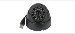
Connect up to x4 IP MJPEG cameras with a proxy via the master module. Only view, no record.
Get SNMP:
Read data from external equipment via SNMP PDU GET (v1/2c)
User keys:
Add users who have access using an RFID reader.
Logic schemes:
Used to specify automatic actions to events that occur in the system.
Timers:
Allows you to plan the events in the system.
Triggers:
Generate events in the system if logic is triggered.
SNMP traps:
Yes
Virtual Math element:
Combine several sensor data and calculate new data
Logic schemes:
Automate events in the system based on alert thresholds and other events.
Power
Energy efficiency:
Grad A (EU Energy level)
Power input (230V AC):
Two inputs option
Power input (24 ÷ 48V DC):
Two inputs option
Power input (12V DC):
Input
Fuse:
1A at the inlet
Min. power consumption:
1 W
Max. power consumption:
10 W
The maximum current load on the relay:
10А
Redundant power supply:
AC/DC; DC/DC or a mix (built-in voltage monitor, voltage range 9-12.6V.)
Reduntant battery:
Optional, ordered separately.
Inputs
Analog port:
x8 (6P6C for connection of an analog sensor. Extendable using CAN bus)
CAN ports:
x2 ports, up to x24 devices in total (Use CAN-12V-1A for connecting more than 12 devices.) (24 max. recommended)
Dry contact inputs:
x32 (contact closures/digital inputs)
Modbus RTU (RS-485):
Using extension VT485m. Optional, ordered separately. Max. line length 1000m
OSDP v2 reader extension:
Using extension VT485R. Optional, ordered separately.
Inputs
USB cameras
Up to 1
IP cameras
Up to x4
Other connectors
Ethernet port:
10/100/1000 Mbps
USB 2.0 Type C:
1
Switch Normal / Recovery:
Returns the device to factory settings
LEDs:
Ethernet ACT & LINK; CAN bus; System status, error and alarm; x2 12V outputs, x2 NC/NO/COM relays
Modem (extension ordered separately)
4G LTE modem:
VT7670 (ordered separately)
Modem modes:
Gateway: Internet access
Access: Internet access over LTE
SMS: SMS notifications
Modem LED:
Modem status
Embedded onboard sensors
Temperature sensor:
+/- 1 °C PCB temperature.
Power supply voltage sensor:
Accuracy (1%) for Main and Reserve power supply
External Memory / Logs
Micro SD memory card slot:
SDXC up to 512 Gb
SD card formatting function (FAT32):
Yes
USB flash drive:
Logs, sensor readings, item settings, etc.
Send system log to e-mail:
Logs, sensor data, elements settings, etc.
Sensor dump files:
Save the per-second samples of analog and discrete sensors
Syslog:
Yes
Send to FTP server:
Logs, sensor data, elements settings, etc.
Maximum amount of log files:
Up to x3 years
Sample rate/period (logs, graphs):
1 second
Environmental characteristics
Operating temperature:
-10 to 70 °C
Storage temperature:
–25 to 85 °C
Operating humidity:
0 to 90 %, non-condensing
Storage humidity:
0 to 95 %, non-condensing
Other Features
Installation:
19” 1U backets included
Casing:
Sheet metal
Dimensions in mm:
440x44x90 (L x W x H)
Weight:
1,6 kg
External chassis grounding:
M4 thread